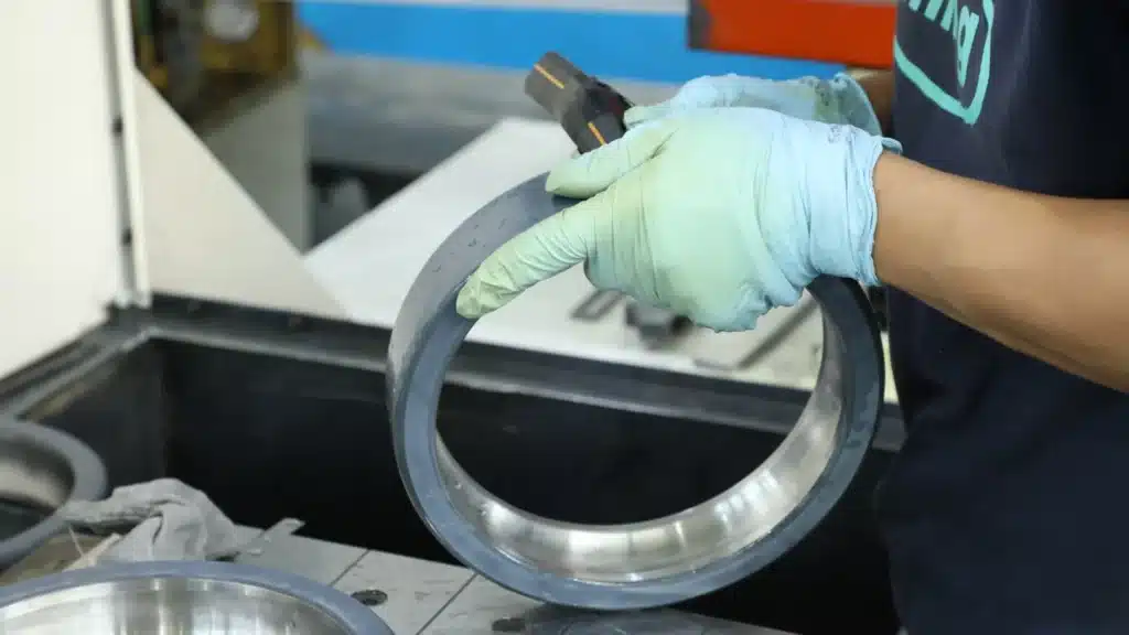

The ceramic coating (Al2O3) is brittle. NEVER use a hammer directly on the coating. Use an Induction Heater to expand the bearing (max 110°C) for shaft installation. Ensure the housing chamfer is smooth to avoid scraping the outer coating. Always verify insulation resistance with a Megohmmeter (>100MΩ) after mounting.
Insulated bearings are expensive—often costing 3 to 5 times more than standard bearings. There is nothing more painful for a maintenance team than hearing that dreaded “crack” sound during installation, or finding out the insulation failed immediately upon startup.
The problem isn’t usually the bearing; it’s the mounting method. Treating a coated bearing like a standard steel bearing is a recipe for disaster.
In this guide, we provide a zero-damage Standard Operating Procedure (SOP) used by OEM assembly lines. You will learn:
- Why ceramic coatings are “Hard but Brittle” (and how to handle them).
- The specific Induction Heater settings to prevent thermal shock.
- The “Chamfer Check” that saves 50% of installations from failure.
- Bonus: A post-installation Multimeter test to confirm success.
The Fragility Factor: Why Ceramic Coatings Crack?
To install these bearings correctly, you must understand the material physics. You are not just handling steel; you are handling a Ceramic-Steel Composite.
Steel vs. Ceramic (The Stiffness Mismatch)
The insulation layer is Aluminium Oxide (Al2O3), plasma-sprayed onto the steel surface.
- Steel is ductile. It can stretch, bend, and deform slightly under stress without breaking.
- Ceramic is extremely hard but brittle. It has zero ductility.
“Think of an insulated bearing like a steel pipe wrapped in a thin layer of glass. If you hit the steel pipe with a hammer, the steel might just dent, but the glass layer will shatter immediately. This is exactly what happens when you use impact force on a coated bearing. No impact. No hammers. Ever.“
Pre-Installation Inspection
Before you even touch a tool, inspect the bearing visually. Shipping damage happens. Look for:
- Micro-cracks: Use a bright light to check the coated surface (usually black or gray).
- Chipped Edges: The edges of the coating are the most vulnerable points. If you see exposed steel on the coated ring, do not install it.
Preparation: Fits, Tolerances & Tools
Do I Need to Change Tolerances? (H7/g6)
A common question we get is: “Since there is a coating, do I need to machine my shaft or housing differently?”
The Answer is No.
Premium manufacturers like TFL and SKF grind the bearing dimensions after or accounting for the coating process. A 6316-C3-VL0241 bearing has the exact same boundary dimensions and tolerances as a standard 6316-C3 bearing.
You should continue to use standard fits, complying with ISO 286 (ISO Code System for Limits and Fits):
- Shaft: k5, m5 (Interference fit)
- Housing: H7, J7 (Transition or Clearance fit)
The Essential Tool Kit
Don’t start the job until you have these items ready:
- Induction Heater: Essential for interference fits.
- Fitting Tool Kit: Sleeves that press the correct ring.
- Protective Gloves: Heat-resistant.
- Megohmmeter (Insulation Tester): For the final check.
- Chamfer File/Polisher: To smooth the housing or shaft lead-in.

Heating Methods: The Induction Heater Rules
For most shaft installations (interference fit), you must heat the bearing to expand the inner ring. However, insulated bearings have a lower tolerance for thermal abuse than standard bearings.
The 110°C Temperature Limit
Rule #1: Never exceed 110°C (230°F).
While bearing steel can technically handle higher temperatures, the thermal expansion coefficient difference between the steel ring and the ceramic coating is the enemy.
- Risk: If you heat the steel too fast or too hot (>120°C), the steel expands faster than the ceramic layer can stretch. The result? The coating cracks or delaminates (peels off).
- Forbidden Methods:
- ❌ Open Flame / Torch: Creates localized “hot spots” that shatter the ceramic instantly.
- ❌ Oil Bath: Dirty oil contains metallic particles. If sludge gets into the micropores of the coating, you lose insulation resistance before you even start.
Sensor Placement (Critical)
Where you place the temperature probe matters.
- For Outer Ring Coated (VL0241): Place the probe on the Inner Ring face. This ensures the bore reaches the correct expansion temperature.
- For Inner Ring Coated (VL2071): Be extremely careful. Place the probe on the Inner Ring face, but set the heater to “Low Power” mode if available.
Do NOT place the induction crossbar (yoke) directly through the bore if the clearance is tight. The magnetic field concentration can overheat the coated surface rapidly. Use a larger yoke or place the bearing flat on the induction plate (if supported) to distribute heat evenly.
Mechanical Mounting: Pressing Without Cracking
Once the bearing is heated (or if you are cold-mounting a small bearing), you need to push it onto the shaft. This is the “Force Path” moment.
The “Forbidden Zone” (Where NOT to hit)
The Golden Rule of Force: Never apply mounting force through the rolling elements (balls/rollers). Force must only pass through the ring being mounted.
- Mounting on Shaft: Apply force ONLY to the Inner Ring.
- Mounting in Housing: Apply force ONLY to the Outer Ring.
For insulated bearings, there is an extra rule: Never apply direct metal-to-ceramic impact.
Using Fitting Tools (Impact Sleeves)
Do not use a drift punch or a hammer directly. You must use a Bearing Fitting Tool Kit (impact rings and sleeves).
The impact ring ensures the force is distributed 360° around the ring face, preventing the bearing from tilting. Tilting leads to the sharp edge of the shaft biting into the bore coating (for VL2071) or the housing edge biting into the outer coating (for VL0241).

[Pitfall Guide] 3 Mistakes That Kill Insulation Instantly
Even experienced mechanics make these mistakes because they treat coated bearings like standard steel bearings. Avoid these three common errors to save your investment.
Mistake #1: The “Chamfer Scrape” (The Silent Killer)
This is the number one cause of failure for Outer Ring Insulated (VL0241) bearings.
If the lead-in chamfer of your motor housing is sharp or has a burr, it acts like a knife edge. As you press the bearing in, the sharp steel housing scrapes a thin line of ceramic coating off the outer ring. You won’t see it because it’s inside the housing, but the insulation is now bridged.
Always run your finger (carefully!) or a shop cloth around the housing bore edge. If it catches the cloth, it will catch the coating. Use a fine file or emery cloth to polish the lead-in chamfer to a smooth 15-degree angle before installation.
Mistake #2: The “Hammer Blow”
We said it before, but it bears repeating: Impact shocks cause micro-cracking. According to ISO 15243 (Rolling Bearings – Damage and Failures), fracture damage initiated by installation impact is irreversible. Even if the coating doesn’t chip off visibly, the internal structure of the ceramic can fracture, lowering the breakdown voltage from 3000V to 500V.
Mistake #3: Dirty Housing ( conductive bridges)
Insulation works by separation. If there are metal filings, old conductive grease, or carbon dust in the housing, these particles can get trapped between the coated ring and the housing. They create a “conductive bridge,” rendering the insulation useless.
Post-Installation: Testing & Lubrication
You’ve mounted the bearing. But is the insulation intact? Don’t wait until the motor is reassembled to find out.
The Multimeter / Megohmmeter Test
You must verify the insulation resistance immediately after mounting the bearing. Following the guidelines of IEEE 43 (Recommended Practice for Testing Insulation Resistance), this test ensures the dielectric integrity is maintained before adding grease or closing the end caps.
- Set your device:
- Standard Multimeter: Set to “Resistance” (Ω) mode.
- Megohmmeter (Recommended): Set to 500V DC.
- Probe placement:
- Probe 1: On the conductive side of the bearing (e.g., Inner Ring or Rolling Elements).
- Probe 2: On the housing (for Outer Coated) or shaft (for Inner Coated).
- Read the value:
- Pass: > 1 MΩ (Multimeter) or > 50 MΩ (Megohmmeter). Ideally, a new installation reads > 100 MΩ.
- Fail: < 0.1 MΩ. This indicates a "Dead Short" caused by a cracked coating or metal debris bridging the gap.
Grease: Conductive or Insulated?
A common myth is that you need special “Non-Conductive Grease” for insulated bearings.
Fact Check: The ceramic coating on the ring provides the insulation. The grease does not need to be electrically rated. Standard high-quality Lithium Complex or Polyurea grease is perfectly fine.
The Only Rule: Do NOT use Conductive Grease (e.g., graphite or copper-based anti-seize) anywhere near the coated surfaces. If conductive paste smears over the coating edge, it will bridge the insulation.
Stop Replacing Bearings Twice.
Installation errors are the #1 cause of insulation failure. But starting with a high-quality, pre-tested bearing helps.
Every TFL Insulated Bearing passes a 100% Spark Test (3000V) before leaving our factory.
Frequently Asked Questions
Can I use an open flame to heat the bearing?
Absolutely not. An open flame creates localized hotspots that exceed 300°C instantly. This rapid expansion will shatter the ceramic coating (which expands slower than steel), causing it to flake off before you even mount the bearing.
What is the maximum heating temperature?
We recommend a maximum of 110°C (230°F). This is sufficient to expand the bore for most interference fits while keeping the thermal stress on the coating within safe limits.
Why does my multimeter show “OL” when testing?
“OL” stands for Open Loop (Infinite Resistance). This is actually a Good Result! It means the insulation layer is doing its job and blocking the current from the meter. If you see a low number (like 50Ω), the insulation is failed.