

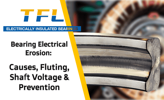
Electrical pitting in bearings occurs when electrical current discharges through the lubricant film between the rolling elements and raceways. Repeated electrical discharge machining, or EDM, creates microscopic craters, damages the lubricant, increases vibration, and may eventually form the parallel washboard pattern known as bearing fluting. This problem is frequently associated with VFD-driven motors, but electrical pitting should be confirmed through raceway inspection, vibration data, electrical measurements, and review of the complete motor and drive system.
If you need help reviewing a failed bearing or selecting an insulated replacement, send the complete bearing model, motor information, quantity, application, speed/load conditions, and failure photos through the TFL Bearing contact form.
Do you often find motor bearings failing earlier than expected, with high repair costs and the same bearing model failing again after replacement? The problem may not be the bearing quality itself. In some VFD-driven motors, hidden electrical erosion continues damaging each replacement bearing because the electrical current path has not been corrected.
The good news is that electrical bearing damage leaves recognizable evidence. Once you understand how shaft voltage develops, identify early warning signs, and use appropriate diagnostic methods, you can distinguish electrical pitting from lubrication failure, contamination, fatigue, and mechanical wear.
This article explains four key areas:
- How VFD-related voltage can create electrical pitting in bearing raceways.
- How repeated EDM damage develops into bearing fluting or washboard patterns.
- How to compare electrical erosion with mechanical wear, corrosion, and fatigue.
- How shaft-voltage measurements, bearing inspection, grounding, filtering, and insulated bearings fit into a complete prevention strategy.
Physical Principle: How PWM Drives and Parasitic Capacitance Create Shaft Voltage
Shaft voltage can become a damaging factor in some electric motor bearing systems. Voltage develops on the motor shaft and may discharge through a bearing toward the motor frame or another grounded component. Each discharge creates a small electrical arc across the lubricant film and rolling contact.
In a VFD-controlled motor, the inverter uses pulse width modulation, or PWM, to control motor speed. The rapid switching produces high-frequency common-mode voltage and steep voltage changes. These electrical effects can couple through capacitance within the motor, cable, rotor, stator, frame, and connected equipment.
Parasitic capacitance exists naturally between motor components, including the stator windings, rotor, shaft, frame, and bearings. It behaves like a network of very small capacitors. Under certain operating conditions, high-frequency voltage can accumulate on the shaft.
The lubricant film inside a bearing can temporarily act as an electrical insulator. When the electrical stress exceeds the film’s insulating capability, a discharge may pass between the rolling element and raceway. This process is commonly described as EDM-related bearing damage.
Factors that may contribute to shaft voltage or bearing-current problems include:
- Fast PWM switching and steep voltage rise times.
- Motor-cable length, cable construction, and shielding.
- Grounding and high-frequency bonding conditions.
- Motor size, design, and internal capacitance.
- Drive configuration and output filtering.
- Lubricant film thickness, bearing speed, load, and operating temperature.
- The grounding path through the motor and connected equipment.
Diagnostic note: A shaft-voltage reading by itself does not prove that destructive bearing current is occurring. The waveform, discharge pattern, measurement method, motor design, grounding arrangement, bearing condition, and current path should be evaluated together.

Electrical Pitting in Bearings: Early Damage Before Fluting
Electrical pitting is generally the initial surface damage created by repeated electrical discharges. Each discharge affects a very small contact area, leaving microscopic pits or craters on the rolling elements or raceways.
At an early stage, the bearing may not yet show a clear washboard pattern. Possible signs include:
- A frosted or dull gray raceway surface.
- Microscopic craters or melted-looking spots.
- Darkened or degraded grease.
- Increasing high-frequency vibration.
- New humming, whining, rumbling, or roughness.
- Repeated failure after a motor is converted to VFD operation.
These signs are not individually conclusive. Dark grease can also result from excessive temperature, oxidation, contamination, incompatible lubricants, or mechanical wear. Raceway frosting and pitting should therefore be compared with vibration data, lubricant condition, shaft-voltage measurements, and other evidence.
How Electrical Pitting Develops into Bearing Fluting
As microscopic discharge marks accumulate, the raceway becomes progressively rougher. Rolling elements repeatedly pass over the damaged areas, increasing vibration and redistributing contact stress.
Under some operating conditions, the damage develops into regularly spaced parallel bands or grooves known as bearing fluting. The pattern is often described as washboarding because the raceway resembles the ridged surface of a washboard.
Bearing fluting is strongly associated with electrical discharge damage, but diagnosis should still consider the entire bearing and motor system. Other wear patterns, vibration-related damage, machining marks, contamination, and false brinelling can sometimes be confused with electrical damage during a quick visual inspection.
Visual Identification: How to Recognize Washboard Fluting
Bearing fluting usually appears as parallel bands or grooves across the raceway. The spacing may be relatively regular, and the marks may extend across part of the load zone or around a larger portion of the raceway.
During inspection, clean the bearing carefully, use strong directional lighting, and compare the inner ring, outer ring, and rolling elements. Record photographs before destructive cleaning or sectioning removes important evidence.
| Feature | Electrical Pitting or Fluting | Mechanical Wear | Corrosion |
|---|---|---|---|
| Pattern | Microscopic pits, frosting, or parallel washboard-like bands | Polishing, smearing, scratching, scoring, or irregular wear | Rust spots, etching, stains, or irregular pits |
| Spacing | Fluting may show repeated or relatively regular spacing | Usually follows load, sliding, contamination, or contact direction | Normally irregular and related to moisture exposure |
| Location | Can affect raceways and rolling elements depending on the current path | Often concentrated in the mechanical load or sliding zone | May appear near exposed surfaces, seals, lubricant pockets, or moisture traps |
| Surface appearance | Frosted, cratered, ridged, or washboard-like | Polished, smeared, dented, cracked, or scratched | Discolored, oxidized, rough, or rusted |
| Supporting evidence | VFD operation, electrical waveforms, high-frequency vibration, darkened grease | Overload, misalignment, poor fit, lubrication failure, or contamination | Water ingress, condensation, damaged seals, or corrosive atmosphere |
Quick inspection checklist:
- Are there parallel or repeated bands on the raceway?
- Does the surface have a frosted or dull appearance?
- Are microscopic pits visible under magnification?
- Is the grease unusually dark, oxidized, or burnt?
- Did vibration or noise increase after VFD installation or modification?
- Is similar damage visible on multiple electrically connected bearings?
- Are mechanical causes such as contamination, fit, load, and misalignment also present?
Inspection tip: Do not diagnose electrical erosion from one visual feature alone. Preserve the bearing, grease, motor settings, cable information, operating history, and vibration records so that the complete failure mechanism can be reviewed.

Microscopic View: How EDM Damages the Raceway
Under magnification, EDM-related damage can look different from rolling-contact fatigue, mechanical indentation, and abrasive wear. Each discharge rapidly heats a microscopic area of metal. The affected material melts or changes structure and then cools quickly.
Individual electrical pits may appear round or irregular, sometimes with a raised or resolidified edge. As repeated discharge events overlap, the raceway can develop a cratered or moon-like surface.
| Feature | EDM-Related Damage | Fatigue Spalling | Brinelling or Indentation |
|---|---|---|---|
| Surface shape | Small pits, craters, frosting, or overlapping melted areas | Flaking, cracking, or larger areas of material separation | Indentations that follow rolling-element spacing or impact points |
| Material appearance | May show localized thermal alteration or resolidified material | Usually associated with rolling-contact fatigue cracks and spalling | Plastic deformation without evidence of electrical melting |
| Cracking | Fine cracks may occur around electrically affected areas | Subsurface and surface fatigue cracks may propagate into a spall | Cracking depends on impact severity and material condition |
| Distribution | May be widespread or linked to the electrical discharge path | Commonly related to the mechanical load zone and contact stress | Often follows rolling-element spacing or isolated impact locations |
Microscopic features that may support an EDM diagnosis include:
- Small overlapping craters.
- Localized melted or resolidified-looking material.
- Frosted surfaces containing many discharge marks.
- Fine cracks around damaged areas.
- Damage occurring outside the expected mechanical load pattern.
Professional metallographic or laboratory analysis may be required when the bearing is part of a critical machine, warranty investigation, repeated failure, or safety-related application.
Failure-analysis note: Surface appearance alone cannot always distinguish electrical pitting from fatigue, contamination, smearing, or corrosion. Use microscopy together with operating history, vibration data, lubricant analysis, and electrical measurements.

Fault Progression: From Lubricant Damage to Bearing Failure
Electrical erosion normally develops progressively rather than causing immediate complete bearing failure. The actual rate depends on the current mechanism, motor design, drive, speed, load, lubricant, bearing size, grounding, operating hours, and environmental conditions.
Early stage: Microscopic electrical pitting begins to alter the raceway and lubricant. The grease may darken, vibration may start increasing, or a faint high-frequency noise may appear. The bearing may still rotate smoothly by hand.
Developing stage: Repeated discharge and rolling contact enlarge the affected area. Frosting, pitting, or fluting becomes visible. Noise, vibration, temperature, and lubricant deterioration may become more noticeable.
Advanced stage: Raceway damage, lubricant breakdown, secondary fatigue, cage stress, and excessive vibration can make the bearing rough and unreliable. Continued operation may cause severe overheating, secondary mechanical damage, or seizure.
| Damage Stage | Possible Symptoms | Recommended Checks | Typical Action |
|---|---|---|---|
| Early | Darkening grease, small vibration change, faint noise, microscopic pitting | Lubricant inspection, vibration trending, electrical measurements, operating history | Confirm the cause and plan corrective action before visible fluting develops |
| Developing | Increasing vibration, rough sound, visible frosting or fluting, rising temperature | Bearing inspection, waveform review, grounding and cable assessment | Schedule bearing replacement and correct the electrical-current path |
| Advanced | Heavy noise, severe vibration, overheating, spalling, seizure risk | Stop-risk assessment, internal inspection, shaft and housing inspection | Remove the motor from service when continued operation is unsafe or unreliable |
Warning signs that require investigation include:
- Dark, oxidized, contaminated, or burnt-smelling grease.
- A repeatable increase in bearing temperature.
- New high-frequency vibration or abnormal motor sound.
- Visible electrical pitting, frosting, or fluting.
- Repeated bearing failure after VFD installation or drive modification.
- Similar damage in motor, gearbox, or driven-machine bearings.
Maintenance tip: Dark grease is a reason to investigate, not a final diagnosis. Record grease condition, temperature, vibration, load, operating hours, and bearing damage before deciding that electrical erosion is the cause.
High-Risk Environments: VFD Motors, Machine Tools, Pumps, and Traction Systems
VFD-driven motors are an important risk group because rapid inverter switching can create high-frequency voltage and current paths. However, the actual risk varies significantly with motor design, cabling, grounding, power level, driven equipment, operating speed, and installation quality.
Machine-tool and spindle motors may combine high speed, frequent speed changes, long or complex cable routes, precision requirements, and costly downtime. These factors make early diagnosis particularly important, but they do not mean every machine-tool bearing failure is electrical.
Fans, pumps, compressors, conveyors, elevators, traction systems, generators, and other inverter-controlled equipment can also experience electrical bearing damage.
| Application | Potential Electrical-Risk Factors | Additional Checks |
|---|---|---|
| Machine tools and CNC spindles | High speed, frequent speed changes, PWM drives, precision bearings, complex cable installation | Balance, preload, lubrication, spindle condition, cable routing, grounding, and waveform analysis |
| Industrial fans and pumps | Continuous VFD operation, cable length, motor-frame grounding, connected piping or structures | Alignment, load, lubrication, cable shielding, bonding, and bearing-current path |
| Elevators and traction systems | Frequent acceleration, deceleration, regenerative operation, high-frequency switching | Motor design, grounding, insulated-bearing position, shaft grounding, and connected equipment |
| Generators and wind equipment | Shaft voltage, converter operation, circulating current, remote maintenance location | Bearing arrangement, grounding, generator design, lubrication, load, and environmental conditions |
| Line-fed motors | Circulating currents, magnetic asymmetry, grounding faults, or connected-machine current paths | Do not exclude electrical damage only because a VFD is not present |
Application note: Cable length and PWM switching can influence electrical stress, but neither factor alone predicts bearing failure. Diagnosis must consider the complete installation rather than applying one universal risk threshold.
Diagnostic Tools: Measuring Shaft Voltage and Bearing Current
Shaft-voltage and bearing-current measurements can help identify electrical discharge conditions, but they must be performed using suitable equipment, an appropriate measurement method, and trained personnel.
Possible diagnostic equipment includes:
- An oscilloscope capable of capturing the relevant high-frequency waveform.
- A suitable shaft-voltage probe, conductive brush, or manufacturer-approved measurement device.
- Appropriate current-measurement equipment where bearing current is being evaluated.
- A reliable high-frequency reference connection to the motor frame.
- Vibration-analysis equipment.
- Infrared or contact temperature-measurement equipment.
- Required electrical PPE and site-specific safety equipment.
Important: Measurement on an operating motor may expose personnel to rotating machinery and hazardous electrical energy. Live measurements should only be performed by qualified personnel following the equipment manufacturer’s instructions, site electrical-safety rules, guarding requirements, and an approved risk assessment.
A typical diagnostic process may include:
- Review the motor, VFD, cable, grounding, bonding, filters, and connected equipment.
- Record the motor operating speed, load, temperature, and drive settings.
- Install the approved shaft-voltage or current-measurement equipment.
- Measure at representative speeds and loads.
- Record waveform shape, repetition, amplitude, and discharge events.
- Compare readings before and after any grounding, filtering, or bearing modification.
- Correlate electrical measurements with vibration and physical bearing damage.
Why One Universal Shaft-Voltage Limit Is Not Reliable
A simple voltage number should not be used as the only pass/fail rule. Different probes, bandwidth settings, grounding methods, motor designs, lubricant films, and measurement locations can produce different readings.
| Measurement Observation | Possible Meaning | Next Step |
|---|---|---|
| Repeating high-frequency shaft-voltage waveform | Possible capacitive coupling or VFD-related common-mode voltage | Review cable, grounding, bonding, motor design, and bearing-current path |
| Fast discharge-like waveform events | Possible lubricant-film breakdown and EDM discharge | Correlate with vibration, grease condition, and raceway inspection |
| Voltage changes after adding a grounding device | The device is influencing the shaft-voltage path | Verify current diversion and protection of connected bearings |
| Low measured voltage but visible fluting | Measurement method, operating condition, or historical event may differ | Review probe contact, bandwidth, past operating data, and other current mechanisms |
Measurement-quality checks include:
- Use the probe and oscilloscope settings recommended for the selected method.
- Keep reference connections short and suitable for high-frequency measurements.
- Verify probe contact and shaft-surface condition.
- Measure under normal operating temperature, speed, and load where safely possible.
- Record several operating points rather than one isolated waveform.
- Compare measurements before and after corrective changes.
- Preserve waveform files and test conditions for later analysis.
Measurement note: Poor probe contact or an unsuitable measurement setup can hide fast discharge events or introduce misleading noise. When the motor is critical, use an experienced motor-diagnostics or condition-monitoring specialist.
What Causes Bearing Fluting?
Bearing fluting causes are usually related to repeated electrical discharge across the rolling contact, followed by vibration and rolling action over the damaged raceway. The original electrical-current mechanism may include:
- Capacitive shaft voltage in a VFD-driven motor.
- High-frequency common-mode current.
- Circulating bearing current caused by motor magnetic asymmetry.
- Rotor-ground current.
- Current passing through the shaft, coupling, gearbox, or driven equipment.
- Inadequate high-frequency grounding or bonding.
- Unsuitable cable shielding or cable termination.
Fluting itself is a developed damage pattern rather than the initial electrical event. Electrical pitting and frosting may appear before the parallel washboard marks become visible.
A reliable diagnosis should answer two separate questions:
- Is the raceway damage electrical rather than mechanical or environmental?
- What current path allowed the discharge to pass through this bearing?
Without identifying the current path, a replacement bearing or grounding device may protect one component while allowing current to damage another bearing, gearbox, encoder, coupling, or driven machine.
How to Select the Correct Prevention Method
There is no single prevention method that is correct for every VFD motor. The solution should match the current mechanism, motor construction, bearing arrangement, and connected equipment.
| Prevention Method | When It May Be Considered | What Must Be Verified |
|---|---|---|
| Outer-ring insulated bearing | When electrical isolation is required between the bearing outer ring and housing | Complete bearing model, coating position, voltage/resistance specification, fit, clearance, cage, and mounting method |
| Inner-ring insulated bearing | When insulation is required between the shaft and bearing inner ring | Shaft fit, induction-heating method, clamping surfaces, current path, and OEM specification |
| Hybrid ceramic bearing | When ceramic rolling elements are suitable for the electrical and mechanical requirements | Speed, load, lubrication, precision, cage, shock load, dimensions, and cost |
| Shaft-grounding ring or brush | When current should be diverted from the shaft through a controlled grounding path | Brush contact, contamination, maintenance, current type, shaft condition, and protection of connected equipment |
| Cable and grounding improvements | When high-frequency bonding, shielding, or cable installation contributes to the problem | Drive and motor manufacturer requirements, termination, grounding path, and system layout |
| Drive output or common-mode filter | When drive-generated electrical stress must be reduced at system level | VFD compatibility, motor cable, switching frequency, motor voltage, and filter specification |
In some systems, an insulated bearing and a shaft-grounding device are used together. In others, cable, grounding, or filtering improvements may be more important. The correct combination should be based on the measured current path and motor manufacturer’s recommendations.
Information Needed for an Insulated-Bearing Review or Quotation
Provide as much of the following information as possible:
- The complete bearing model and all suffixes.
- Bore, outside diameter, and width.
- Required quantity.
- Motor manufacturer, motor model, and nameplate photos.
- Drive-end or non-drive-end installation position.
- VFD manufacturer, model, switching settings, and motor-cable information.
- Operating speed, radial load, axial load, and duty cycle.
- Internal clearance, cage, seals, lubricant, and temperature.
- Required outer-ring, inner-ring, or hybrid insulation arrangement.
- Raceway, grease, and failed-bearing photographs.
- Available vibration, shaft-voltage, or bearing-current measurements.
Need Help Reviewing Electrical Pitting or Fluting?
Send the complete bearing model, motor and VFD details, quantity, operating conditions, and available damage photos. TFL Bearing can help review the insulated-bearing requirements.
Stop Electrical Erosion Before It Causes Repeated Failure
Electrical pitting in bearings can begin with microscopic discharge marks and progress into frosting, fluting, lubricant damage, vibration, noise, secondary fatigue, and premature failure.
The complete process often involves VFD switching, capacitive coupling, common-mode voltage, grounding, cabling, motor construction, and the electrical path through connected machinery. This is why repeatedly installing the same standard bearing may not solve the problem.
Early warning signs such as darkened grease, increased high-frequency vibration, new bearing noise, electrical pitting, or washboard fluting provide an opportunity to investigate before severe secondary damage occurs.
Insulated bearings can interrupt current through the selected bearing position, but they should be used as part of a complete electrical and mechanical review. Grounding, bonding, cable construction, shaft grounding, filters, motor design, lubrication, load, and alignment may also affect the final solution.
For machine-tool applications, review our insulated bearings for machine-tool motors, browse the complete TFL product range, or submit your bearing and motor information for review.
Frequently Asked Questions
What is electrical pitting in bearings?
Electrical pitting occurs when an electrical discharge passes through the lubricant film between a bearing’s rolling elements and raceways. Each discharge creates a microscopic pit or crater. Repeated pitting can damage the lubricant, increase vibration, and develop into visible fluting.
What is the difference between electrical pitting and bearing fluting?
Electrical pitting describes the individual microscopic discharge marks created on bearing surfaces. Bearing fluting is a more developed washboard-like pattern that can form after repeated electrical discharge and rolling contact. Pitting may be present before visible fluting appears.
What causes bearing fluting?
Bearing fluting is commonly caused by repeated electrical discharge through a bearing. Possible current mechanisms include VFD-related capacitive shaft voltage, common-mode current, circulating current, rotor-ground current, or current passing through connected equipment. The exact current path must be identified before selecting a solution.
How can I tell whether a bearing has electrical damage?
Possible signs include microscopic craters, frosted raceways, parallel fluting marks, darkened grease, high-frequency vibration, and repeated failure in a VFD-driven motor. These signs should be confirmed with physical inspection, operating history, vibration analysis, lubricant examination, and suitable electrical measurements.
Does black grease prove that a bearing has electrical erosion?
No. Dark or black grease may result from electrical discharge, excessive temperature, oxidation, contamination, incompatible lubricants, or mechanical wear. It is an important warning sign but not conclusive proof of electrical erosion.
Can shaft voltage be measured with an oscilloscope?
Yes. A suitable oscilloscope and shaft-voltage probe can be used to record shaft-voltage waveforms. Because the test may involve operating machinery and hazardous electrical energy, it should be performed by qualified personnel using an approved measurement method and site safety procedure.
Is there one shaft-voltage limit that proves EDM damage?
No universal voltage threshold applies to every motor and measurement method. Probe type, bandwidth, grounding, lubricant film, motor design, operating load, and waveform shape all influence the result. The reading should be interpreted together with bearing-current evidence and physical damage.
What is the best way to prevent bearing electrical erosion?
The correct method depends on the electrical current path. Possible measures include an outer-ring or inner-ring insulated bearing, hybrid ceramic bearing, shaft-grounding ring, improved high-frequency grounding and bonding, shielded motor cables, or drive filtering. Some systems require a combination of measures.
Can I replace a standard bearing with an insulated bearing?
Many insulated versions use the same main boundary dimensions as the corresponding standard bearing, but the complete model, internal clearance, cage, seals, precision, speed, load, coating position, insulation specification, and mounting method must still be verified.
What information is needed for an insulated-bearing quotation?
Send the complete bearing model, dimensions, quantity, motor make and model, drive-end or non-drive-end position, application, speed, load, VFD information, internal clearance, cage, seals, insulation requirement, drawings, and available photos of the damaged bearing and raceways.