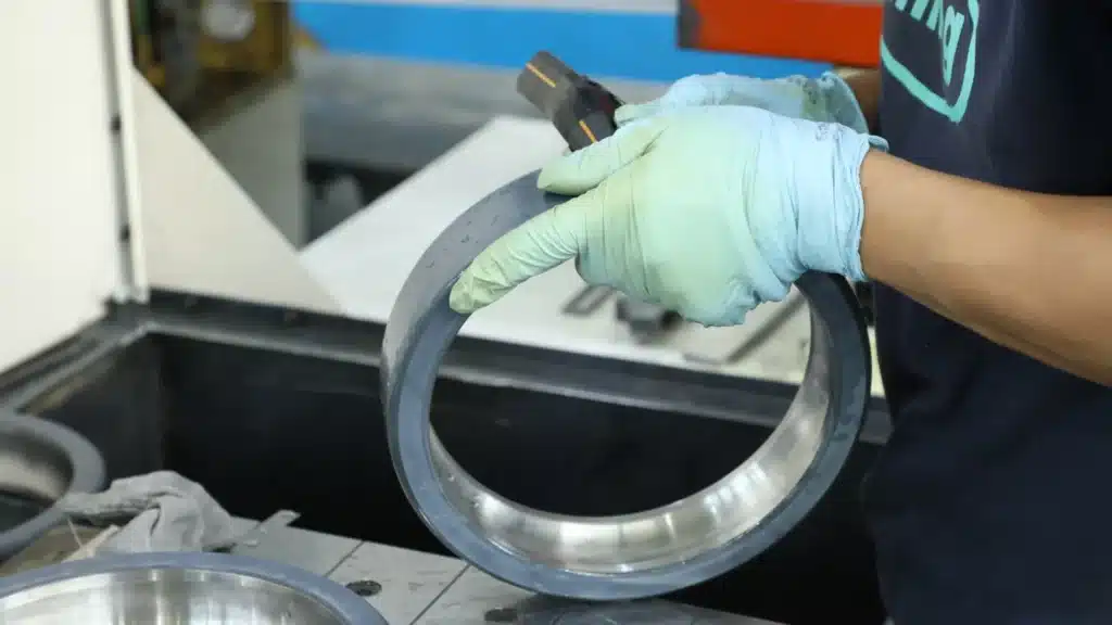


One or two insulated bearings in a VFD motor should be selected from the bearing-current mechanism and the complete electrical return path—not from a fixed DE/NDE rule. The review must include the VFD, motor frame, shaft, drive-end and non-drive-end bearings, grounding and bonding, coupling, encoder, gearbox, pump or other driven equipment.
Short Answer
One insulated bearing can interrupt an internal circulating-current loop because that loop requires a conductive path through both motor bearings. It does not automatically protect the remaining conductive bearing from capacitive shaft-voltage discharge. A common protection architecture for larger VFD motors is therefore one insulated bearing at one end and a maintained shaft-grounding device at the opposite end, subject to the motor OEM and system design. Two insulated bearings can protect both motor bearing positions, but they do not eliminate shaft potential or every conductive path; current may still discharge through a coupling, encoder, gearbox, pump or driven-machine bearing. Correct cabling, shield termination, high-frequency bonding and measurement must be reviewed before the bearing order is approved.

Why VFD Use Alone Does Not Decide the Bearing Arrangement
A variable-frequency drive can increase bearing-current risk because its pulse-width-modulated output produces rapid voltage transitions and high-frequency common-mode current. However, the resulting current does not always follow the same path. ABB separates modern AC-drive bearing currents into circulating current, shaft-grounding current and capacitive discharge current. Motor size, frame and shaft grounding, cable construction, shield bonding, drive switching characteristics and the driven-machine connection influence which mechanism becomes important.
This is why “install an insulated NDE bearing on every VFD motor” is not a dependable engineering rule. NDE insulation is common in some OEM designs, but DE/NDE location alone does not define the electrical function. Begin with TFL’s explanation of why VFD motors may require bearing-current protection, then map the installed system before selecting hardware.
Three Bearing-Current Mechanisms to Separate
| Mechanism | Typical current path | What one insulated bearing can do | What shaft grounding can do | Main residual risk |
|---|---|---|---|---|
| High-frequency circulating current | One motor bearing → shaft → opposite motor bearing → motor frame | Interrupts the internal loop because both bearing paths are required for continuous circulation | Does not by itself open the internal circulating loop | A grounding device installed across the insulated end can recreate an unintended conductive route |
| Capacitive shaft-voltage discharge / EDM current | Shaft → conductive bearing oil film breakdown → motor frame | Protects the insulated position, but the remaining conductive bearing can still discharge | Provides a controlled low-impedance route before the voltage breaks down the bearing lubricant film | Poor contact, contamination or maintenance failure can leave the grounding path ineffective |
| Shaft-grounding or external return current | Motor frame or shaft → motor bearing/coupling/driven machine → inverter return path | Can block one section of the path but may redirect current through another conductive component | Can control shaft potential when bonding and placement are correct | Encoder, gearbox, pump or driven-machine bearings may become the lowest-impedance path |
These mechanisms can coexist. A configuration that blocks circulating current may still need a controlled shaft-discharge path. Conversely, a grounding ring can control shaft voltage but cannot be assumed to interrupt a circulating-current loop that passes through both motor bearings.
Bearing Protection Starts Before the Bearing
ABB identifies three broad approaches to high-frequency bearing-current control: establish proper cabling and earthing, break the bearing-current loop, and damp high-frequency common-mode current. Bearing insulation addresses only one part of that system.
| System field | Good review practice | Why it matters |
|---|---|---|
| Motor cable | Use the drive and motor manufacturer’s recommended symmetrical multicore cable | Asymmetrical PE arrangements can increase unwanted current and magnetic imbalance |
| Cable shield termination | Maintain a continuous conductive shield with 360-degree termination at both ends where specified | A long pigtail or incomplete termination has higher high-frequency impedance |
| Motor-to-driven-equipment bonding | Use a short, wide, low-inductance high-frequency bonding path where required | Equalizing frame potential can reduce current through motor and driven-machine bearings |
| Frame contact surfaces | Remove paint, corrosion and contamination from intended bonding points | A visually connected conductor can still have excessive high-frequency impedance |
| Drive-side mitigation | Review common-mode chokes, filters or other drive-specific measures with the drive supplier | Some devices reduce common-mode current but do not discharge shaft voltage by themselves |
Correct cabling and bonding do not automatically eliminate the need for insulated bearings, but they can reduce the electrical stress and prevent the bearing from becoming the unintended return path. Always follow the VFD, motor and filter manufacturer’s product-specific installation instructions.
Option 1: One Insulated Bearing
One insulated bearing is often reviewed when the primary objective is to interrupt an internal circulating-current loop. Because that loop passes through both motor bearings in opposite directions, opening one bearing path can stop continuous circulation and protect both motor bearing positions from that particular mechanism.
However, the shaft can still accumulate capacitively coupled voltage. If the opposite bearing remains conductive, shaft voltage may discharge through that bearing when the lubricant film breaks down. One insulated bearing therefore should not be described as complete protection against every VFD-related bearing current.
Before ordering one insulated bearing, verify:
- which current mechanism is being interrupted;
- whether the OEM specifies DE or NDE insulation;
- whether the opposite end has a controlled shaft-discharge path;
- whether the coupling or driven machine grounds the shaft;
- the complete bearing type, dimensions, cage, clearance, fit and insulation construction.
Option 2: One Insulated Bearing Plus Shaft Grounding
Insulation interrupts a current path; shaft grounding creates a controlled path. The two measures can therefore be complementary. In a commonly used larger-motor architecture, an insulated or hybrid bearing interrupts circulating current at one end while a shaft-grounding device at the opposite end drains capacitive shaft voltage away from the remaining conductive bearing.
AEGIS manufacturer guidance uses this opposite-end arrangement as a best-practice example for larger VFD motors. It is not a universal motor standard or a substitute for the motor OEM’s drawing. Installing the grounding device at the insulated end can bridge the intended open circuit and allow circulating current to pass through the opposite conductive bearing.
A grounding ring or brush also requires ongoing maintenance. Check:
- shaft surface condition and any conductive coating requirement;
- fiber or brush contact, wear and contamination;
- paint, oxide, grease, oil or moisture at the grounding path;
- low-impedance bonding from the device to the motor frame;
- installation position relative to the insulated bearing;
- inspection and replacement interval.
For a more focused comparison, review shaft grounding ring vs insulated bearing.
Option 3: Two Insulated Bearings
Two insulated bearings can isolate both motor bearing positions from the frame. This may be required by an OEM design, a special machine architecture, a difficult grounding environment or an application where both motor bearings must be electrically separated.
Two insulated bearings do not eliminate shaft potential. If the motor shaft remains connected through a metallic coupling, encoder, tachometer, gearbox, pump or driven machine, the remaining potential may discharge through those components. ABB notes that driven-machine or gearbox bearings can sometimes be damaged before the motor bearings when they become part of the return path.
A two-bearing strategy should therefore include:
- a drawing of every conductive shaft and frame connection;
- continuity checks across the coupling and auxiliary equipment;
- a defined path for shaft potential where required;
- before-and-after voltage or current evidence;
- inspection of driven-machine bearings, not only the motor bearings.
One or Two Insulated Bearings: Practical Decision Matrix
| Observed or specified condition | Configuration commonly reviewed | Reason | Approval boundary |
|---|---|---|---|
| OEM drawing specifies one insulated NDE bearing | Preserve the original DE/NDE architecture | The motor design may already use one end to interrupt a defined loop | Match the complete designation and confirm whether shaft grounding is also specified |
| Large motor with suspected HF circulating current and shaft-voltage discharge | One insulated bearing plus shaft grounding at the opposite end | Insulation opens the circulating loop while grounding controls capacitive discharge | Confirm mechanism, OEM instructions, device capacity, placement and maintenance |
| Small or medium motor with mainly capacitive shaft-voltage discharge | Shaft-grounding solution may be reviewed first | A controlled discharge path may protect the bearings without changing the bearing architecture | Do not assume motor power alone proves the mechanism; measure and follow OEM guidance |
| Both motor bearings already insulated by OEM design | Retain both insulated bearings and review the whole shaft train | The design may intentionally isolate the motor bearings | Confirm coupling, encoder, gearbox, pump and driven-equipment current paths |
| Metallic coupling to a well-grounded gearbox or pump | System-level bonding, grounding and bearing protection review | The driven equipment may complete the return path | Do not approve two motor insulated bearings without checking driven-machine bearings |
| Repeated fluting but current mechanism is unknown | Do not select hardware yet | The wrong remedy can move the current path rather than remove it | Inspect, measure and document the installed system first |
| Insulated coupling and no verified conductive external shaft path | One or two insulated bearings depending on the internal mechanism and OEM design | The external return path may already be interrupted | Verify real continuity; do not rely only on the coupling description |
This matrix is a review framework, not a universal selection standard. The motor OEM, drive supplier, grounding-device manufacturer and responsible engineer may impose more specific requirements.
DE/NDE Placement Must Still Match the Mechanical Bearing Arrangement
An electrically suitable position can still be mechanically wrong. DE and NDE bearings may have different functions, and one end may locate the shaft axially while the other allows thermal expansion. The two positions may also use different bearing types.
| Mechanical field | What to confirm before changing DE/NDE insulation |
|---|---|
| Bearing function | Locating end, non-locating end, axial-load support and thermal-expansion path |
| Bearing type | Deep-groove ball, cylindrical roller, angular-contact or other arrangement |
| Radial internal clearance | CN, C3, C4 or application-specific clearance after fit and operating temperature |
| Cage and lubrication | Cage material/design, grease or oil method, relubrication and speed capability |
| Insulation construction | Outer-ring coating, inner-ring coating or ceramic rolling elements |
| Fits and tolerances | Shaft/housing interference, precision class, coating allowance and mounting method |
| Temperature and stabilization | Operating temperature, thermal growth and dimensional-stabilization suffixes |
Do not move an insulated-bearing specification from NDE to DE—or replace a cylindrical roller bearing with a ball bearing—merely to simplify the electrical layout. Preserve the original mechanical architecture unless the motor design is formally revised.
Coupling, Encoder, Gearbox and Driven-Equipment Risk
The motor is only one part of the current loop. A metallic coupling can connect the shaft to a well-grounded gearbox, compressor, fan, pump or generator. Encoders and tachometers may contain small bearings that are especially vulnerable when they become the remaining discharge route.
Record whether each coupling is metallic, elastomeric, insulated or fitted with conductive elements. Verify continuity with an appropriate method rather than relying only on the product name. Also document frame-to-frame bonding, auxiliary shafts, seals, gear meshes and any grounding brush already installed on the driven equipment.
Shaft-Voltage Measurement: Useful Evidence with Important Limits
Shaft-voltage measurement can reveal fast discharge events and help compare the system before and after corrective work. Fluke notes that the motor should be energized, rotating and warmed to its normal operating temperature, and that measurements can be taken at both drive and non-drive ends with a suitable shaft-voltage probe and high-bandwidth instrument.
| Measurement or observation | What it can support | What it cannot prove alone |
|---|---|---|
| Shaft-voltage waveform | Presence of shaft potential and rapid discharge behavior | The exact damage already present in the bearing |
| Events per second | Frequency of captured discharge events under the tested operating state | Performance under every speed, load and temperature condition |
| DE vs NDE comparison | Differences between motor ends and possible placement clues | A complete current-loop diagnosis without system continuity and grounding data |
| Before/after comparison | Whether a grounding, bonding or insulation change reduced the measured behavior | Long-term reliability without inspection and condition monitoring |
| Direct bearing-current measurement | Verification of a suspected current loop when performed correctly | A routine test with a standard multimeter |
ABB states that direct high-frequency bearing-current work needs wide-bandwidth equipment, specialized sensors and experienced personnel. A single voltage peak from a general-purpose meter should not decide whether the motor needs one or two insulated bearings. Combine electrical measurement with bearing inspection, vibration, lubricant condition, speed, load and temperature records.
Use TFL’s shaft voltage measurement guide to organize the test record.
Configuration Evidence and RFQ Checklist
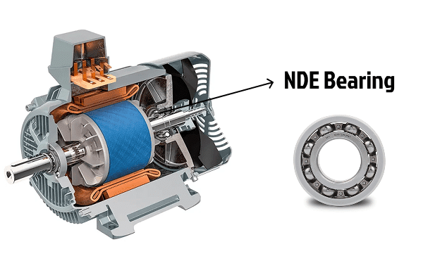
- Record the full motor, VFD and driven-equipment identification, including OEM document revision.
- Photograph and copy the complete DE and NDE bearing designations.
- Identify the locating and non-locating bearing positions and all mechanical suffixes.
- Draw the motor frame, shaft, bearings, coupling, encoder, gearbox, pump and grounding paths.
- Record cable type, length, shield termination, PE arrangement and frame bonding.
- Describe any grounding ring, brush, insulated coupling, filter or common-mode device already installed.
- Attach shaft-voltage, continuity, vibration and bearing-inspection evidence where available.
- State quantity, delivery country, required date, urgency and whether a sample or partial shipment is useful.
- List required drawings, electrical test reports, inspection records, certificates and traceability documents.
- Ask TFL to separate confirmed matches, confirmed differences, assumptions and unresolved approval fields.
For quotation, combine this engineering evidence with the insulated bearing RFQ checklist. TFL can then review insulated-bearing stock, low-MOQ or sample options, production lead time, available documents and configuration-specific replacement candidates.
Technical References
- Fluke: Measuring Motor Shaft Voltage Discharges — supports warmed-up operating measurements, DE/NDE test access, fast waveform capture and event-count context.
- SKF Evolution: Prevention of Electric Erosion in Bearings — supports electrical erosion, high-frequency VFD bearing-current context and insulated-bearing mitigation.
- AEGIS Manufacturer Guidance: VFD Bearing Protection — supports the manufacturer’s opposite-end insulated-bearing and shaft-grounding architecture. It is presented as manufacturer best practice, not a universal standard.
ABB, Fluke, SKF and AEGIS names are used nominatively for neutral source identification. These references do not imply affiliation, authorization, a universal DE/NDE rule or automatic approval of a TFL replacement configuration.
FAQ
Is the NDE bearing always the insulated bearing in a VFD motor?
No. NDE insulation is common in some OEM arrangements, but the correct position depends on the current mechanism, mechanical bearing functions, coupling, grounding and motor documentation.
Does one insulated bearing protect both motor bearings from circulating current?
It can interrupt an internal circulating-current loop because that loop requires conductive paths through both bearings. It does not automatically protect the remaining conductive bearing from capacitive shaft-voltage discharge.
Should both motor bearings be insulated?
Only when the OEM design or system review supports it. Two insulated bearings protect both motor bearing positions but may leave coupling, encoder, gearbox, pump or driven-machine bearings as alternative discharge paths.
Do I still need a shaft-grounding ring with one insulated bearing?
Possibly. The insulated bearing interrupts a circulating loop, while shaft grounding controls capacitive shaft voltage at the remaining conductive end. The need depends on the measured mechanism and OEM protection architecture.
Where should the shaft-grounding device be installed?
In a common larger-motor manufacturer arrangement, it is installed at the end opposite the insulated bearing. Final placement must follow the motor OEM and grounding-device instructions.
Can two insulated motor bearings move the risk to the gearbox or pump?
They do not actively push current elsewhere, but the remaining shaft potential may discharge through another conductive route such as a metallic coupling or driven-machine bearing. Review the whole equipment train.
Can correct VFD cabling eliminate the need for insulated bearings?
Symmetrical cable, continuous shielding, 360-degree termination and high-frequency bonding can reduce unwanted current and frame-potential differences. Whether bearing insulation is still required depends on motor size, current mechanism and OEM design.
What should I send for a DE/NDE configuration review?
Send motor and VFD data, complete DE/NDE bearing numbers, mechanical bearing functions, coupling and driven-equipment diagram, grounding/bonding details, measurement evidence, quantity, destination, required date and document requirements.
Need help choosing one or two insulated bearings?
Send TFL your motor and VFD details, complete DE/NDE bearing designations, coupling and driven-equipment path, grounding arrangement, measurement evidence, quantity, delivery country, required date and document needs. We can check insulated-bearing stock, confirm lead time, review low-MOQ or sample options and prepare a configuration-aware quote that separates confirmed matches from open technical points.