

However, one type of noise often refuses to fit neatly into that three-step method. The motor produces a continuous humming or buzzing sound. Adding grease or replacing the lubricant does not solve it. When the bearing is opened, the raceway shows washboard-like bands and the grease may be darkened or carbonized.
In this situation, bearing electrical erosion should be high on the suspect list. In bearing literature, the discharge mechanism is commonly described as electrical discharge machining (EDM) damage.
This is not the same as ordinary wear, rolling-contact fatigue, or poor lubrication. The basic mechanism is simple: current passes through the rolling contact and repeatedly discharges across the lubricant film, producing microscopic arcs that damage the metal surface. The machine may continue to run while the raceways are already developing pits and fluting. It is a hidden failure that can progress long before the outside of the motor reveals the full severity.
This article explains where the current comes from, what marks it leaves, what the ear and vibration instruments can detect, how to avoid a false diagnosis, and what to do after the damage is confirmed.
How Does Electrical Current Enter a Motor Bearing?
In a conventionally supplied, healthy three-phase motor, the phase system is intended to be balanced and the bearing is primarily a mechanical component—not an electrical conductor. In practice, however, shaft voltage can develop and produce bearing current under several operating or installation conditions.
| Common cause | Typical field condition |
|---|---|
| Variable-frequency drive (VFD) | PWM output creates high-frequency common-mode voltage, and current seeks a return path. |
| Magnetic asymmetry | Uneven air gap, winding asymmetry, or magnetic-circuit imbalance induces voltage along the shaft. |
| Static charge accumulation | Belt drives, airflow, or process friction can build charge on the shaft. |
| Incorrect welding-current return path | During repair welding, the return clamp is positioned so that welding current passes through a bearing. |
VFD operation is now one of the most common backgrounds. Fast PWM switching generates high-frequency common-mode voltage. If the motor, cable shield, frame, driven machine, and grounding system do not provide a suitable low-impedance return path, part of the current can flow through a bearing to the housing, shaft, or connected equipment.
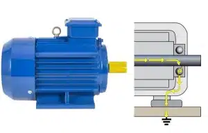
The bearing is not the only possible path. Parasitic capacitances, the motor frame, cable shield, protective-earth conductors, couplings, gearboxes, and driven-machine bearings can all share or redirect current. Nevertheless, the thin lubricant film in a bearing can become a vulnerable breakdown point. Once the voltage across that film exceeds its instantaneous withstand level, a discharge occurs.
For a more detailed explanation of the electrical mechanisms, see our guide to shaft voltage in electric motors.
This is why washboard fluting and darkened grease should not automatically be blamed on poor lubricant quality. In an electrically damaged bearing, current is repeatedly arcing across the rolling contact.
One Critical Mark: Inspect the Raceway and Grease
For electrical erosion, teardown evidence is usually more reliable than sound alone. The characteristic washboard pattern does not appear overnight. It develops as many local discharges create microscopic craters, after which repeated rolling contact organizes and enlarges the damaged areas.
Each discharge can affect both the lubricant and the raceway. The local arc temperature is extremely high. Grease near the discharge zone may darken, dry out, smell burnt, or show carbonized material. At the same time, the discharge can leave pin-point craters, commonly described as electrical pitting or EDM craters.
These effects do not always occur in a clean sequence. Field inspections often show darkened grease, carbonized deposits, and microscopic pits at the same time. It is therefore misleading to assume that the grease must turn black first and the raceway pits must appear later.
As discharges continue, the number of pits increases and the surface pattern becomes more regular. The damage may develop into parallel transverse bands across the rolling path, repeated around the circumference. This rhythmic washboard appearance is known as fluting. Our comparison of electrical pitting versus fluting explains how the early crater stage differs from the developed groove pattern.
A common mistake is to judge the failure only by grease color. Grease may be only moderately dark while clear fluting is already visible. Raceway pattern is stronger evidence; grease discoloration is an important supporting clue, but it is not proof by itself. Heat, oxidation, contamination, wear debris, and incompatible greases can also darken lubricant.
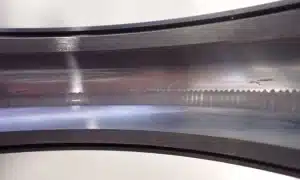
Use strong lighting and magnification. Clean and document the raceways before drawing conclusions. If tactile inspection is necessary, wear clean gloves and avoid touching the working surface with bare fingers, which can introduce moisture, salts, and contamination.
The number of fluting bands may sometimes show a relationship with rolling-element motion, but it does not have to equal the number of rolling elements. Band spacing depends on several interacting factors, including discharge repetition, speed, bearing geometry, load, lubricant-film behavior, and structural dynamics. Do not estimate the number of electrical discharges with a simple multiplication formula.
In practical field diagnosis, evenly distributed, repeated, relatively regular washboard bands are sufficient to raise strong suspicion. Confirm the conclusion by combining the physical marks with operating history, VFD configuration, grounding, vibration trends, and electrical measurements.
Two Warning Signals Before Teardown
The raceway mark becomes visible only after the bearing is opened. Before teardown, technicians normally develop suspicion from sound and vibration. One signal can be heard; the other is clearer with an instrument.
Signal 1: A Continuous, Relatively Stable Humming or Buzzing Sound
Electrical bearing damage can produce a persistent, relatively uniform humming, buzzing, whining, hissing, or rough running sound. It may grow louder with speed. Unlike a distinct impact from advanced spalling, it can sound more continuous; unlike a simple lubrication complaint, regreasing often fails to suppress it because the root cause is not only the lubricant film.
However, an important warning is necessary: a humming sound does not prove electrical erosion.
PWM excitation from a VFD can create high-frequency electromagnetic and structural vibration that travels through the motor frame and bearing housings. The sound may appear to come from the bearing even when the raceway has not yet developed fluting.
Where the motor, process, and electrical design permit it, qualified personnel may compare VFD operation with a short test on an approved sinusoidal or line-frequency supply. If the noise falls sharply, the dominant source may be VFD-related electromagnetic or structural excitation rather than established raceway fluting.
Even when the noise changes during the comparison, the result is not a complete diagnosis. Existing damage can remain in the bearing while the excitation and sound signature change. Use sound to create a hypothesis—not to deliver the final verdict.
Signal 2: Characteristic Changes in the Vibration Spectrum
When pitting and fluting have developed, vibration data may show increased broadband high-frequency energy, repetitive impacts, and peaks near bearing defect frequencies such as BPFO, BPFI, BSF, or FTF and their harmonics or sidebands. Envelope or demodulation analysis can make repetitive impacts easier to see.
These frequencies must be calculated from bearing geometry and operating speed or obtained from a verified bearing database. They cannot be reduced to “shaft speed multiplied by the number of rolling elements.”
More importantly, BPFO or BPFI peaks are not unique signatures of electrical erosion. They indicate mechanically developed raceway or rolling-element damage and can also arise from fatigue, contamination, lubrication failure, or installation defects. The electrical root cause must be established from the complete evidence set.
For many maintenance teams, the absence of advanced instruments should not delay a justified inspection. Visible fluting remains strong teardown evidence. A persistent abnormal sound and darkened grease increase suspicion, but neither is mandatory and neither is independently conclusive.
Supplementary Confirmation: Measure Shaft Voltage and Discharge Activity
A more direct confirmation method is to measure shaft-to-frame voltage and observe discharge waveforms with suitable high-bandwidth equipment and an approved shaft probe or brush. Repetitive, sharp discharge events can confirm that an electrical current path exists. Because incorrect probing can produce misleading results or expose personnel to rotating and energized equipment, this work should be performed by trained specialists.
Our detailed article on detecting electrical erosion before catastrophic failure covers shaft-voltage checks, discharge detection, vibration trending, ultrasound, temperature, and teardown inspection.
Avoid Misdiagnosis: Electrical Erosion Versus Other Failure Modes
The same humming sound may come from VFD-related structural excitation or from a fluted raceway. Dark grease may result from electrical discharges, but it may also result from overheating, oxidation, contamination, wear debris, or lubricant incompatibility. The following table shows typical tendencies—not a forensic verdict.
| Feature | Electrical erosion | Wear | Fatigue spalling | Poor lubrication |
|---|---|---|---|---|
| Typical sound | Continuous humming, buzzing, whining, or rough noise | Rubbing, scraping, or sandy noise | Impacts, clicking, or irregular roughness | May be subtle early; can develop squeal, rumble, or roughness |
| Grease condition | May darken, burn, dry, or contain fine debris; not proof by itself | May darken from wear debris | Often normal or moderately contaminated until damage advances | May dry, harden, separate, emulsify, oxidize, or leak |
| Raceway surface | Fine craters, frosting, or regular washboard fluting | Polishing, scoring, smearing, or abnormal shine | Irregular cracks, pits, and spalled areas | Smearing, scoring, heat discoloration, or secondary fatigue |
| Effect of regreasing | Does not remove the electrical cause or repair damaged raceways | Usually does not reverse established wear | No corrective effect on spalled material | Can improve an early lubrication problem when the correct lubricant and quantity are used |
| Progression | Continues while the damaging current path remains | Usually progressive | Can accelerate suddenly after crack growth and spalling begin | May be reversible early, but can become permanent after surface damage |
Two practical rules are useful:
If correct relubrication produces a clear and sustained improvement, investigate lubrication first. If relubrication does not help and teardown reveals regular fluting—especially together with darkened grease and a VFD background—investigate electrical erosion.
In the uncertain middle ground, compare operating conditions, review VFD and grounding history, inspect the lubricant, trend vibration and temperature, and then decide whether teardown and electrical measurement are required. Our motor-bearing lubrication guide can help separate lubricant problems from electrically driven damage.
What Should You Do After Electrical Erosion Is Confirmed?
Once the raceway has developed fluting, replacing only the grease without correcting the current path treats the symptom, not the cause. New lubricant is quickly exposed to the same electrical environment.
A practical response normally follows three steps.
Step 1: Replace the Damaged Bearing
A bearing with established fluting has irreversible raceway damage. Continued operation must be assessed against vibration, temperature, process criticality, secondary damage, and safety risk. In most cases, replacement should be scheduled promptly; severe vibration, overheating, spalling, or seizure risk may require immediate shutdown.
Step 2: Investigate the Electrical System
Review the VFD, motor cable, shield termination, protective earth, high-frequency bonding, motor frame, coupling, driven equipment, output filter, switching settings, and any recent drive or wiring changes. Follow the motor and drive manufacturers’ instructions. Do not change VFD parameters solely from a general article.
Step 3: Block or Divert the Current Path
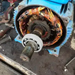
The aim is to give unwanted current a controlled route or prevent the bearing from completing the circuit.
| Protection method | Application principle |
|---|---|
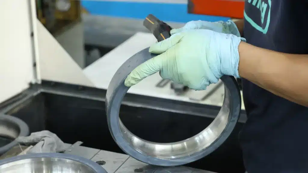
| Electrically insulated bearing | A ceramic coating on the outer or inner ring interrupts the intended bearing-current loop. The complete system must still be reviewed so that current is not transferred to another bearing or driven component. |
| Hybrid ceramic bearing | Silicon-nitride rolling elements electrically isolate the rolling contacts and can provide additional high-speed benefits. Compare hybrid ceramic and coated insulated bearings before selection. |
| Shaft grounding brush or ring | Provides a low-impedance path from shaft to frame. It requires correct installation, clean contact surfaces, inspection, and maintenance. |
| Grounding, bonding, shielding, and output filtering | Reduces common-mode voltage or provides a controlled high-frequency return path through cable shields and bonded structures rather than through bearings. |
| Conductive lubricant | A specialized, application-dependent measure—not a universal cure. It may alter current distribution rather than eliminate current. Use only when specifically approved by the motor, bearing, and lubricant suppliers. |
There is no single solution for every motor. New motor design, overhaul, retrofit, motor size, voltage class, coupling arrangement, environmental contamination, and the type of bearing current all affect the correct strategy. In many larger VFD systems, an insulated bearing at one end is combined with a maintained grounding device at the other, but the exact arrangement must follow the motor and drive design.
Our comparison of a shaft grounding ring versus an insulated bearing explains where each method works and why combined protection is sometimes required.
Remember the Relationship—and the Correct Diagnostic Order
Think of the high-risk evidence as a triangle:
Raceway fluting + persistent abnormal humming or buzzing + darkened or carbonized grease
The three clues do not have to appear with equal severity. Visible fluting alone is sufficient to justify a serious electrical investigation, but even fluting should be interpreted with microscopy, operating history, and electrical context when the failure has warranty, safety, or root-cause implications.
Keep the order correct:
- Listen and locate the abnormal sound.
- Where approved and safe, compare VFD and sinusoidal/line-frequency operation to identify an electromagnetic-noise component.
- Inspect vibration, temperature, lubricant, and operating history.
- Open the bearing and inspect the raceways, grease, cage, and rolling elements.
- Confirm the electrical path with suitable shaft-voltage or current measurements when required.
- Replace the damaged bearing and correct the electrical root cause.
A sound that resembles electrical damage does not prove that the raceway is already fluted. Once fluting is visible, however, the response must move beyond lubrication and include bearing replacement plus electrical-system correction.
This diagnostic series began with narrowing down abnormal motor-bearing noise. This article explains what to do when the evidence points toward an electrical cause. A related field problem is covered in our guide to motor-bearing overheating.
Frequently Asked Questions
Does black grease prove that a motor bearing has electrical erosion?
No. Dark or black grease is an important warning sign, but it can also result from oxidation, excessive temperature, contamination, wear debris, incompatible lubricants, or an overly long service interval. Confirm electrical erosion from raceway marks, operating history, vibration, and electrical measurements.
Does a continuous humming sound prove that the bearing is fluted?
No. A VFD can create electromagnetic and structural noise that travels through the motor frame and bearing housing. Sound should trigger investigation, not serve as the final diagnosis.
Can regreasing repair electrical pitting or fluting?
No. Correct grease may temporarily alter sound or temperature, but it cannot restore metal removed by EDM discharges. Established pitting and fluting are irreversible.
What is the strongest field evidence of electrical bearing damage?
Regular washboard fluting, fine electrical craters, or a frosted raceway—combined with a credible current path and operating history—provides strong evidence. For critical failures, use microscopy, lubricant analysis, vibration data, and shaft-voltage or current measurements.
Should I use a shaft grounding ring or an insulated bearing?
The answer depends on the current mechanism, motor size, grounding design, environment, maintenance capability, and connected equipment. Grounding devices divert current; insulated or hybrid bearings interrupt a path. Many critical systems use a coordinated combination rather than a single device.
References and Technical Notes
- IEEE 841-2021, severe-duty process-industry induction motors. This is the current edition that replaced the 2009 edition cited in the original source article.
- GB/T 21707-2018, measurement methods for shaft current in converter-fed motors.
- ABB Technical Guide No. 5, Bearing Currents in Modern AC Drive Systems.
- Public technical guidance from major bearing and motor manufacturers on bearing electrical erosion, electrical pitting, fluting, grounding, and insulated bearings.
This article provides general failure-diagnosis guidance and does not replace machine-specific instructions. Always combine vibration analysis, teardown findings, electrical measurements, lubrication condition, and operating history. VFD settings, rewiring, grounding modifications, and live measurements must be handled by qualified personnel in accordance with the equipment manufacturers’ procedures.
Need help selecting a replacement or protection strategy? Review our insulated motor bearing solutions or send the motor, bearing, VFD, speed, load, and failure details to TFL for a technical review.